
Video Event Recorders This was a proof of concept project to integrate: an IEEE 1482.1 compliant event recorder, FRA compliant vigilance system (Alerter) and an audio/video recorder into a single on board system. The goal was to correlate the operator's actions and the on-board systems performance with the video and audio feeds. The prototype consisted of a 32-bit single board computer running embedded XP and a video server shoehorned into an IEEE compliant event recorder box. The C# application running in a .NET framework took the event recorder data from a serial feed and combined it with the video frames into a watermarked data structure. This data was then stored in a crashworthy memory module for later analysis. IEEE 1482.1 Compliant Event Recorders Unlike aviation the rail industry did not have a standard for event recorders until the IEEE published 1482.1-1999 IEEE Standard for Rail Transit Vehicle Event Recorder . As a contributing member to the working group DCA has a detailed understanding of the standard's requirements and the reasons for them. The resultant event recorder was a distributed multi-processor architecture controlled by a central processor module operating as a master state machine. Each input module (power supply, analog, frequency and digital) could withstand the IEEE's +/- 4,000 volt and 80 joule transient surges. The system was capable storing weeks of data from 4 frequencies, 32 analog and 96 digital channels in a crashworthy memory module. Network Based Event Recorders The use of redundant sensors to provide independent operational information for event recording is a good thing up to a point. Once the critical parameters (throttle, braking, warning devices) are directly obtained it is more cost effective to receive data from existing sensors on other systems. DCA has been involved in all stages of implementing network configurations. From simple RS-232/422/485 serial links (EMD Export Locomotives) to the more involved LonWorks (NYCTA R142 and LIRR) and TCN/MVB (Houston) networks we can assist in creating or vetting the Interface Control Documents to ensure robust communication. Crashworthy Data Storage The first rail transit requirement for crashworthy memory came in New York City Transit Authority's R142 procurement in the mid-90's. Those survivability requirements greatly influenced the eventual IEEE standard's requirements. The freight rail industry is about to get its first crashworthy regulation. The Federal Railroad Administration (FRA) has issued the Final Draft 2005-04-30 of its Notice of Proposed Rule Making (NPRM). The following compares the two crashworthy requirements.
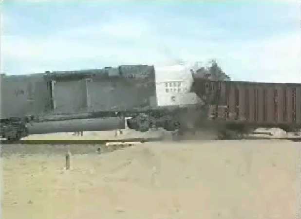
The significant difference is the FRA's increased temperature and doubled fire duration. The catch with the FRA regulation is the requirement for a single crashworthy memory to under go the entire sequence of tests in order to qualify. With capacities from single megabytes to multiple gigabytes, DCA can assist you in crash hardening your data. Crash Testing The FRA conducted field trials with a locomotive crashing into 37 gravel filled hopper cars (30 MPH), a logging truck loaded with redwoods (50 MPH) and a couple of rolls of steel (50 MPH). Despite predictions to the contrary the locomotive immediately climbed on top of the hopper cars... 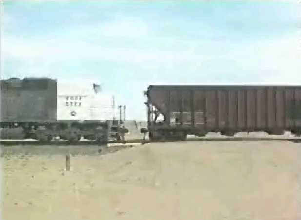
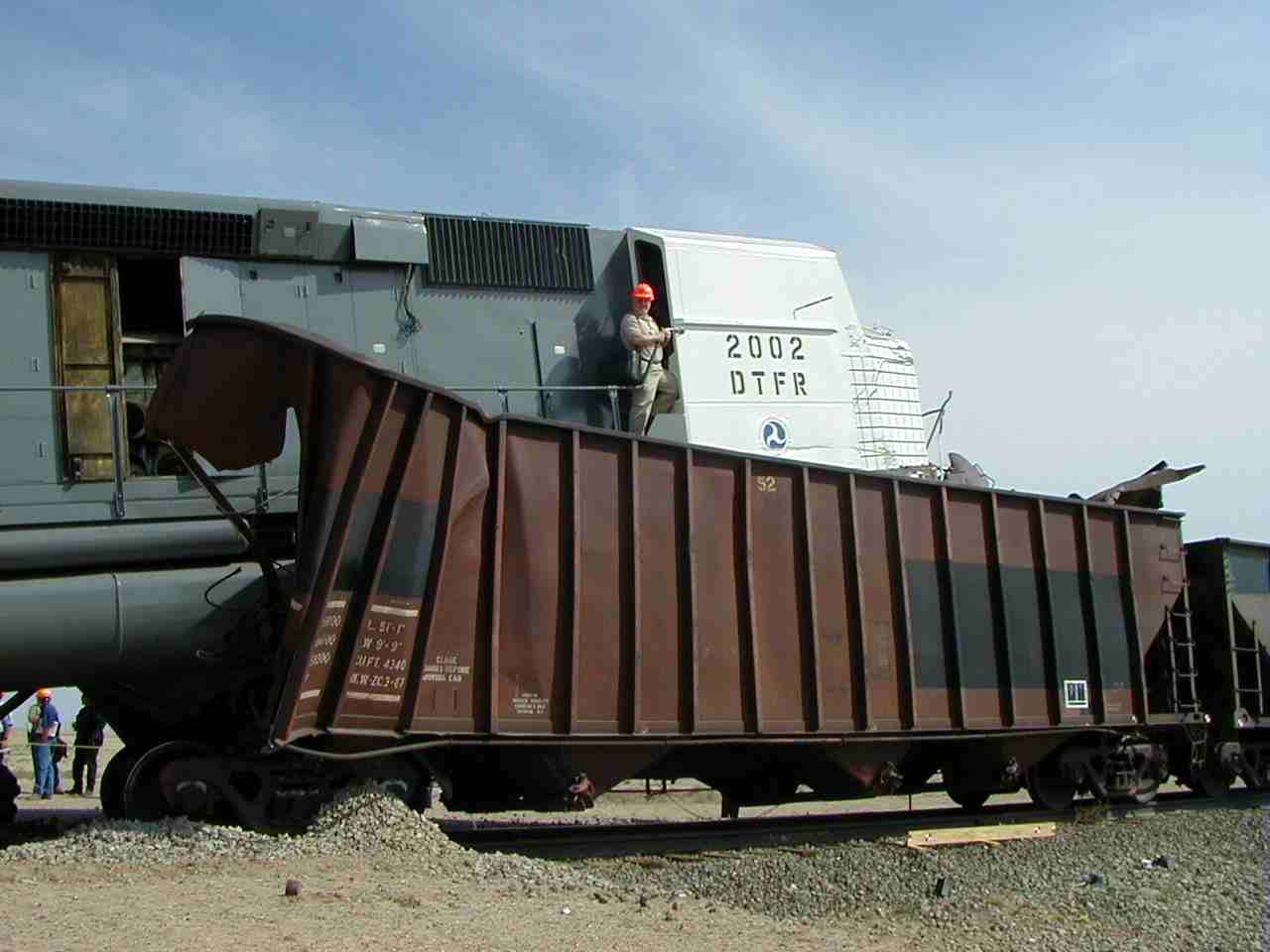
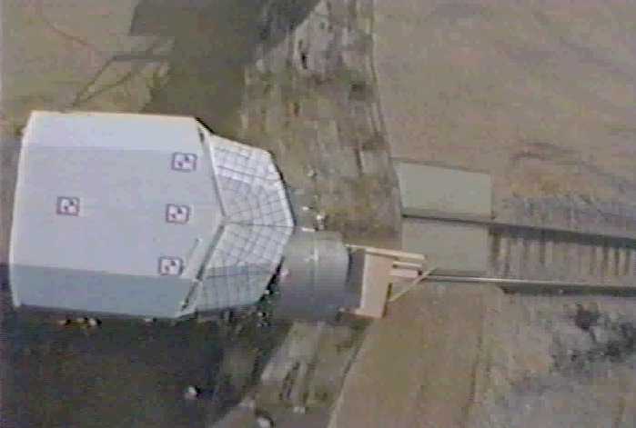
Rammed through the redwoods as if they weren't there... 


The event recorder was placed directly inline with the steel coil, behind the collision post, in the nose below the operator. 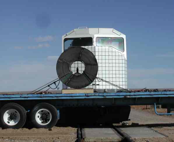 And the locomotive becomes one with the roll of steel... 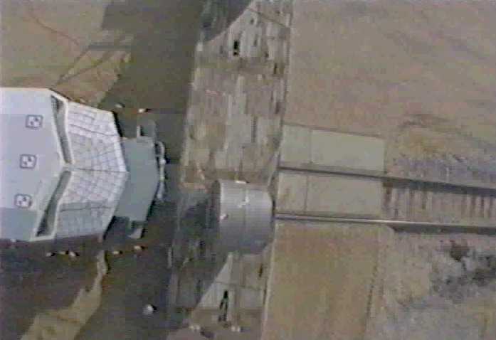
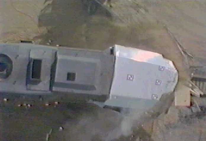
It took two weeks to extract the event recorder however the data was intact.  Event Recorder Data Analysis Software Event recorder data is very densely packed and can quickly bring traditional data analysis tools (spreadsheets, databases) to their knees. 65,000 records or more in a day's operation is pretty typical. DCA can bring over 10 years of data reduction and display experience to work for you. The example shown below is a 1.7 hour segment of GO Transit locomotive operation displayed in coordinated graphical and table formats. 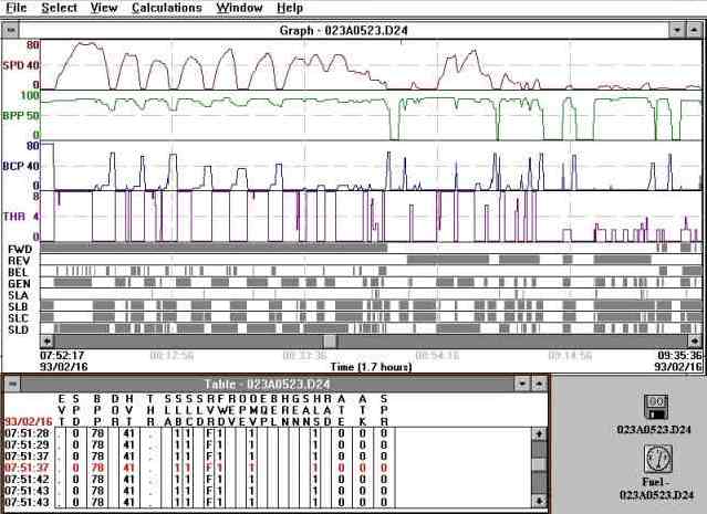 Setup/Download and Real-time Display Software Human Machine Interface (HMI) software has been a focus of DCA for over 20 years. It is imperative to keep the interface simple and intuitive. Traditional Window's applications such as the one shown below 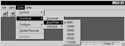
are quickly giving way to browser based displays. These HMI utilities are capable of status and fault reporting, real-time data display, system calibration, and remote system software updates.
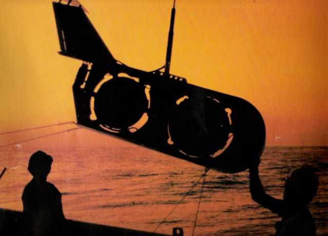
Arctic Oceanographic Buoy The Arctic Oceanographic Buoy (AOB) is an expendable probe that measures the background acoustic noise level under the arctic ice. AOB uses a DSP processor to measure sound pressure levels in 1/3 octave bandpass filters and transmits the data via an ARGOS satellite transmitter. The AOB is launched by shooting it out of airplane with the equivalent of a 12 gauge shot gun blast. It would then deploy a parachute to orient the shock absorbing material on the bottom. After it landed, and stopped rolling, it would expel the ice drill, acoustic package, processor/transmitter assemblies. The ice drill would burrow through over 10 feet of arctic ice and drag the acoustic package into the water. The antenna would cap the hole and the system would begin processing and transmitting data. All of this was packaged into a 4" diameter, 4' long tube! The electronics package was so robust that after a fall trial the unit resumed transmitting in the spring after surviving an entire arctic winter. Bring us your toughest packaging problem and DCA will find a way to make it work! Deployable Acoustic Calibration System The Deployable Acoustic Calibration System (DACS) is an accurate sound source for simulating submarine signatures in training exercises. The system used a depth compensated ringshell projector with an acoustic feedback loop to produce very accurate tones. The tone synthesizer and feedback measurements are DSP based with a serial communications link between the projector and a rack mounted PC. The DACS console is another example of an HMI using serial communications and a friendly menu driven application. 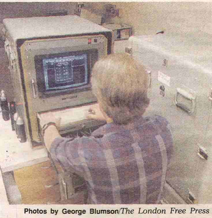
Towed Acoustic Tactical Trainer The Towed Acoustic Tactical Trainer (TATT) is an acoustic augmentation system for existing anti-submarine warfare training towed bodies. TATT features a microprocessor controlled console with an alpha-numeric display and simple keypad interface. The operator entered the required depth, tone frequencies and amplitudes and the system calculated the required ringshell drive voltage. This system uses a predictive model to compensate for changing ringshell frequency response due to changes in depth. Tow/Wave Simulator The Tow/Wave Simulator (TWS) was used to measure the drag forces on sonobuoy components under flow and wave conditions. The simulator featured a 40-foot hydraulic cylinder that ran the length of a 20-foot deep indoor pool. Optical shaft encoders measured the speed of the test body. The hydraulic valve was controlled by an 8-bit micro-controller that received its data via an IEEE-488 interface from either a PC-AT or HP-85 Basic Controller. |